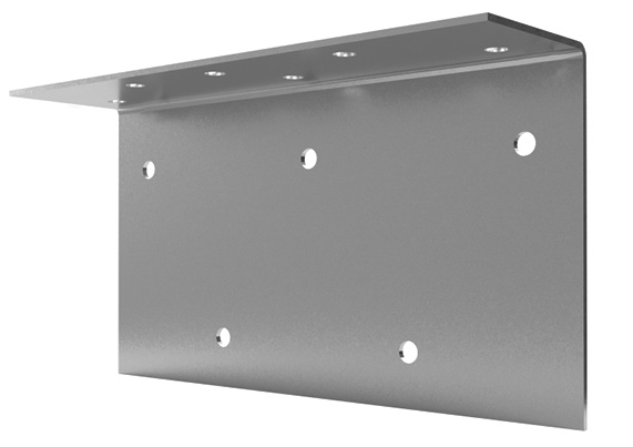
The multi-use secure clip (MB) is used in a variety of different applications including head-of-wall, joist connections, securing hips, rafters and trusses, reinforcing header connections, bridging, etc. It is constructed with mill certified 57 ksi steel designed to resist vertical and lateral loads. Pre-punched guide holes are provided in each leg for superior installation efficiency.
Features
- Variety of lengths available
- Loads based on #10 screws
- Pre-punched guide holes
- No labor used cutting scrap or angle
MB Submittal Download
Material Composition
- Mill certified steel
- ASTM A653/A653M
- 54 mil
- 57 ksi yield strength
- 65 ksi tensile strength
- G60 galvanized coating
- 68 mil
- 57 ksi yield strength
- 65 ksi tensile strength
- G90 galvanized coating
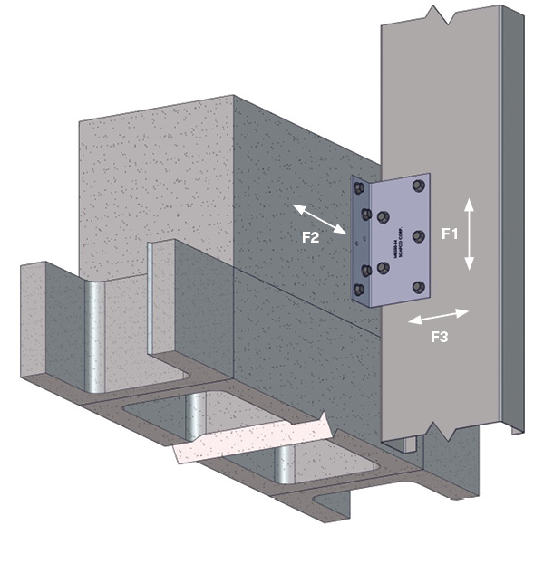
Allowable Loads
| Part No. | Stud Properties | F1 Allowable Loads (lbs) | F2 Allowable Loads (lbs) | F3 Allowable Loads (lbs) | |||||
|---|---|---|---|---|---|---|---|---|---|
| Mil | Gauge | Fy (ksi) | 2 #10 Screws | 3 #10 Screws | 2 #10 Screws | 3 #10 Screws | 2 #10 Screws | 3 #10 Screws | |
| MB350 | 33EQS | 20 | 57 | 402 | 603 | 206 | 310 | 206 | 310 |
| 33 | 20 | 33 | 353 | 530 | 168 | 251 | 168 | 251 | |
| 43EQS | 18 | 57 | 635 | 952 | 280 | 420 | 280 | 420 | |
| 43 | 18 | 33 | 526 | 789 | 219 | 328 | 219 | 328 | |
| 54 | 16 | 50 | 1068 | 1602 | 396 | 594 | 396 | 594 | |
| 68 | 14 | 50 | 1510 | 2266 | 499 | 749 | 499 | 749 | |
| 97 | 12 | 50 | 2261 | 2420 | 712 | 965 | 712 | 965 | |
| Maximum Allowable Clip Capacity | Max F1 = 2420 lbs | Max F2 = 965 lbs | Max F3 = 965 lbs | ||||||
| Part No. | Stud Properties | F1 Allowable Loads (lbs) | F2 Allowable Loads (lbs) | F3 Allowable Loads (lbs) | ||||||||
|---|---|---|---|---|---|---|---|---|---|---|---|---|
| Mil | Gauge | Fy (ksi) | 2 #10 Screws | 4 #10 Screws | 5 #10 Screws | 2 #10 Screws | 4 #10 Screws | 5 #10 Screws | 2 #10 Screws | 4 #10 Screws | 5 #10 Screws | |
| MB550 | 33EQS | 20 | 57 | 402 | 804 | 1005 | 206 | 413 | 516 | 206 | 413 | 516 |
| 33 | 20 | 33 | 353 | 707 | 884 | 168 | 335 | 419 | 168 | 335 | 419 | |
| 43EQS | 18 | 57 | 635 | 1269 | 1587 | 280 | 560 | 700 | 280 | 560 | 700 | |
| 43 | 18 | 33 | 526 | 1052 | 1315 | 219 | 437 | 547 | 219 | 437 | 547 | |
| 54 | 16 | 50 | 1068 | 2136 | 2671 | 396 | 792 | 855 | 396 | 792 | 855 | |
| 68 | 14 | 50 | 1510 | 2980 | 2980 | 499 | 855 | 855 | 499 | 855 | 855 | |
| 97 | 12 | 50 | 2261 | 2980 | 2980 | 712 | 855 | 855 | 712 | 855 | 855 | |
| Maximum Allowable Clip Capacity | Max F1 = 2980 lbs | Max F2 = 855 lbs | Max F3 = 855 lbs | |||||||||
| Part No. | Stud Properties | F1 Allowable Loads (lbs) | F2 Allowable Loads (lbs) | F3 Allowable Loads (lbs) | ||||||||
|---|---|---|---|---|---|---|---|---|---|---|---|---|
| Mil | Gauge | Fy (ksi) | 2 #10 Screws | 4 #10 Screws | 7 #10 Screws | 2 #10 Screws | 4 #10 Screws | 7 #10 Screws | 2 #10 Screws | 4 #10 Screws | 7 #10 Screws | |
| MB750 | 33EQS | 20 | 57 | 402 | 804 | 1407 | 206 | 413 | 722 | 206 | 413 | 722 |
| 33 | 20 | 33 | 353 | 707 | 1237 | 168 | 335 | 597 | 168 | 335 | 597 | |
| 43EQS | 18 | 57 | 635 | 1269 | 2221 | 280 | 560 | 980 | 280 | 560 | 980 | |
| 43 | 18 | 33 | 526 | 1052 | 1841 | 219 | 437 | 765 | 219 | 437 | 765 | |
| 54 | 16 | 50 | 1068 | 2136 | 3739 | 396 | 792 | 1387 | 396 | 792 | 1387 | |
| 68 | 14 | 50 | 1510 | 3021 | 5286 | 499 | 998 | 1740 | 499 | 998 | 1740 | |
| 97 | 12 | 50 | 2261 | 4521 | 6100 | 712 | 1424 | 1740 | 712 | 1424 | 1740 | |
| Maximum Allowable Clip Capacity | Max F1 = 6100 lbs | Max F2 = 1740 lbs | Max F3 = 1740 lbs | |||||||||
| Part No. | Stud Properties | F1 Allowable Loads (lbs) | F2 Allowable Loads (lbs) | F3 Allowable Loads (lbs) | ||||||||
|---|---|---|---|---|---|---|---|---|---|---|---|---|
| Mil | Gauge | Fy (ksi) | 2 #10 Screws | 5 #10 Screws | 9 #10 Screws | 2 #10 Screws | 5#10 Screws | 9 #10 Screws | 2 #10 Screws | 5 #10 Screws | 9 #10 Screws | |
| MB950 | 33EQS | 20 | 57 | 402 | 1005 | 1809 | 206 | 516 | 929 | 206 | 516 | 929 |
| 33 | 20 | 33 | 353 | 884 | 1590 | 168 | 419 | 754 | 168 | 419 | 754 | |
| 43EQS | 18 | 57 | 635 | 1587 | 2856 | 280 | 700 | 1260 | 280 | 700 | 1260 | |
| 43 | 18 | 33 | 526 | 1315 | 2367 | 219 | 547 | 984 | 219 | 547 | 984 | |
| 54 | 16 | 50 | 1068 | 2671 | 4807 | 396 | 991 | 1740 | 396 | 991 | 1740 | |
| 68 | 14 | 50 | 1510 | 3776 | 6100 | 499 | 1248 | 1740 | 499 | 1248 | 1740 | |
| 97 | 12 | 50 | 2261 | 5652 | 6100 | 712 | 1740 | 1740 | 712 | 1740 | 1740 | |
| Maximum Allowable Clip Capacity | Max F1 = 6100 lbs | Max F2 = 1740 lbs | Max F3 = 1740 lbs | |||||||||
Screw shear values are based on the SSMA Screw Table with the following notes:
- Allowable loads have not been increased for wind, seismic activity, or other factors.
- The allowable loads are based on the steel properties of the members being connected, per AISI S100.
- The nominal strength of the screw must be at least 3.75 times the allowable loads.
- Values include a 3.0 factor of safety.
- Penetration of screws through joined materials should not be less than three exposed threads. Install and tighten screws in accordance with the screw manufacturer’s recommendations.
- Allowable loads indicated on the table(s) are for force in single direction only. The designer shall use the combined forces check as required by AISI S100 if more than one force is applied to the connection.
Quantity / Order Information
| Part No. | Length | Qty / Bucket | Lbs / Bucket |
| MB350-54 | 3 ½” | 100 | 25 |
| MB350-68 | 3 ½” | 100 | 31 |
| MB550-54 | 5 ½” | 100 | 38 |
| MB550-68 | 5 ½” | 100 | 48 |
| MB750-54 | 7 ½” | 75 | 39 |
| MB750-68 | 7 ½” | 75 | 49 |
| MB950-54 | 9 ½” | 50 | 33 |
| MB950-68 | 9 ½” | 50 | 42 |