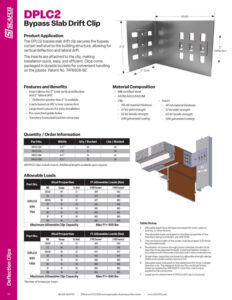
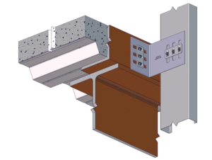
The DPLC2 slide clip attaches the bypass curtain wall stud to the building structure, allowing for vertical deflection and lateral drift. The insert is pre-installed to the clip, making installation quick, easy, and efficient. Clips are packaged in durable buckets for easy handling on the jobsite. Patent No. 7478508-B2

Features & Benefits
- Insert allows for 2” total vertical deflection and 2” lateral drift
– Greater than 2” are available - Loads based on #12 screws
- Large insert pieces for easy installation
- Pre-punched guide holes
- Transfers horizontal loads into structure
DPLC2 Submittal Download
Material Composition
- Mill certified steel
- ASTM A653/A653M
- Clip
– Material thickness: 118 mil
– Yield strength: 57 ksi
– Tensile strength: 65 ksi
– G90 galvanized coating - Insert
– Material thickness: 97 mil
– Yield strength: 57 ksi
– Tensile strength: 65 ksi
– G90 galvanized coating
Allowable Loads
| Model No. | Stud Thickness | F1 Allowable Loads (lbs) | ||||
|---|---|---|---|---|---|---|
| Mils | Gauge | Fy (ksi) | 2 #12 Screws | 3 #12 Screws | ||
| DPLC2 550 750 |
33EQS | 20 | 57 | 429 | 643 | |
| 33 | 20 | 33 | 377 | 565 | ||
| 43EQS | 18 | 57 | 677 | 905 | ||
| 43 | 18 | 33 | 561 | 841 | ||
| 54 | 16 | 50 | 905 | 905 | ||
| 68 | 14 | 50 | 905 | 905 | ||
| 97 | 12 | 50 | 905 | 905 | ||
| 118 | 10 | 50 | 905 | 905 | ||
| Maximum Allowable Clip Load | 905 | 905 | ||||
| Model No. | Stud Thickness | F1 Allowable Loads (lbs) | ||||
|---|---|---|---|---|---|---|
| Mils | Gauge | Fy (ksi) | 2 #12 Screws | 3 #12 Screws | ||
| DPLC2 950 1150 |
33EQS | 20 | 57 | 429 | 643 | |
| 33 | 20 | 33 | 377 | 565 | ||
| 43EQS | 18 | 57 | 677 | 677 | ||
| 43 | 18 | 33 | 561 | 841 | ||
| 54 | 16 | 50 | 895 | 895 | ||
| 68 | 14 | 50 | 895 | 895 | ||
| 97 | 12 | 50 | 895 | 895 | ||
| 118 | 10 | 50 | 895 | 895 | ||
| Maximum Allowable Clip Load | 895 | 895 | ||||
Table Notes
- Allowable loads have not been increased for wind, seismic or other factors.
- Screw spacing and edge distance shall not be less than 3 x d. (d=nominal screw diameter)
- The allowable loads are based on the steel properties of the members being connected, per AISI Section E4.
- When connecting materials of different thicknesses or tensile strength (Fu), the lowest applicable values should be used.
- The nominal strength of the screw must be at least 3.75 times the allowable loads.
- Penetration of screws through joined materials should not be less than 3 exposed threads. Install and tighten screws in accordance with the screw manufacturer’s recommendations.
- Screw shear capacities are based on allowable strength design (ASD) and include a safety factor of 3.0.
- Applied loads may be multiplied by ¾ for seismic or wind loading, per AISI A 5.1.3
- Loads are for attachment of DPLC2 Drift Clip to stud only. It is the responsibility of the designer to check the bending in the short leg of this clip and its connection to the structure members, depending on the direction of forces.
Quantity / Order Information
| Model No. | Width | Qty / Bucket | lbs / Bucket |
|---|---|---|---|
| DPLC2-550 | 5 ½” | 20 | 56 |
| DPLC2-750 | 7 ½” | 15 | 48 |
| DPLC2-950 | 9 ½” | 15 | 53 |
| DPLC2-1150 | 11 ½” | 15 | 58 |
Note: All clips include insert. Additional lengths available upon request.