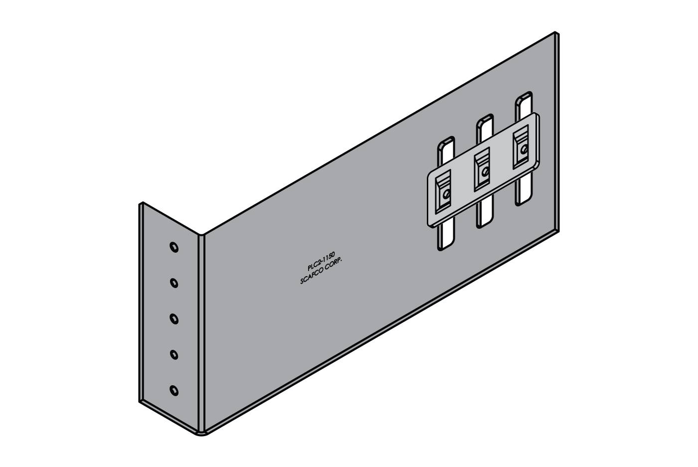
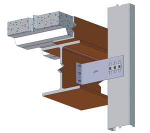
The PLC2 bypass slab slide clip attaches the bypass curtain wall stud to the building structure, allowing for vertical deflection while maintaining lateral rigidity. The insert is attached to the clip, making installation quick, easy, and efficient. Clips are packaged in durable buckets for convenient handling on the jobsite. Patent No. 7478508-B2
Features
- Insert allows for 2″of total vertical deflection
– Deflection greater than 2” is available - Loads based on #12 screws
- Large insert piece for easy installation
- Pre-punched guide holes
- Transfers horizontal load into structure
- Maintains lateral rigidity
- Eliminates bridging within 12” of support connection
- Thicker steel from improved lateral resistance for in-plane seismic forces and strengthened weld capacity to the structure
Material Composition
- Mill certified steel
- ASTM A653/A653M
- Clip
– Material thickness: 118 mil
– Yield strength: 57 ksi
– Tensile strength: 65 ksi
– G90 galvanized coating - Insert
– Material thickness: 97 mil
– Yield strength: 57 ksi
– Tensile strength: 65 ksi
– G90 galvanized coating
Allowable Loads
| Part No. | Stud Thickness | F1 Allowable Loads (lbs) | ||||
|---|---|---|---|---|---|---|
| Mils | Gauge | Fy (ksi) | 2 #12 Screws | 3 #12 Screws | ||
| PLC2 550 750 |
||||||
| 33EQS | 20 | 57 | 429 | 643 | ||
| 33 | 20 | 33 | 377 | 565 | ||
| 43EQS | 18 | 57 | 677 | 1015 | ||
| 43 | 18 | 33 | 561 | 841 | ||
| 54 | 16 | 50 | 1139 | 1709 | ||
| 68 | 14 | 50 | 1610 | 1975 | ||
| 97 | 12 | 50 | 1975 | 1975 | ||
| 118 | 10 | 50 | 1975 | 1975 | ||
| Maximum Allowable Clip Load | 1975 | 1975 | ||||
| Part No. | Stud Thickness | F1 Allowable Loads (lbs) | ||||
|---|---|---|---|---|---|---|
| Mils | Gauge | Fy (ksi) | 2 #12 Screws | 3 #12 Screws | ||
| PLC2 950 1150 |
||||||
| 33EQS | 20 | 57 | 429 | 643 | ||
| 33 | 20 | 33 | 377 | 565 | ||
| 43EQS | 18 | 57 | 677 | 1015 | ||
| 43 | 18 | 33 | 561 | 841 | ||
| 54 | 16 | 50 | 1139 | 1650 | ||
| 68 | 14 | 50 | 1650 | 1650 | ||
| 97 | 12 | 50 | 1650 | 1650 | ||
| 118 | 10 | 50 | 1650 | 1650 | ||
| Maximum Allowable Clip Load | 1650 | 1650 | ||||
Table Notes
- Allowable loads have not been increased for wind, seismic activity, or other factors.
- The allowable loads are based on the steel properties of the members being connected, per AISI S100.
- The nominal strength of the screw must be at least 3.75 times the allowable loads.
- Penetration of screws through joined materials should not be less than three exposed threads. Install and tighten screws in accordance with the screw manufacturer’s recommendations.
- Screw shear capacities are based on allowable strength design (ASD) and include a safety factor of 3.0.
- Allowable loads indicated on the table(s) are for force in single direction only. The designer shall use the combined forces check as required by AISI S100 if more than one force is applied to the connection.
- The designer shall check the bending in the short leg of clip.
Quantity / Order Information
| Part No. | Width | Qty / Bucket | Lbs / Bucket |
|---|---|---|---|
| PLC2-550 | 5 ½” | 30 | 54 |
| PLC2-750 | 7 ½” | 25 | 54 |
| PLC2-950 | 9 ½” | 20 | 50 |
| PLC2-1150 | 11 ½” | 20 | 57 |