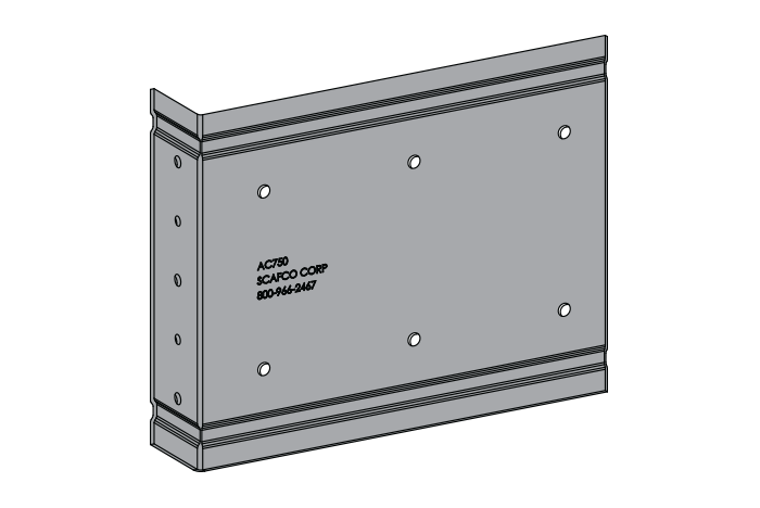
The bypass slab secure clip (AC) connects an exterior wall stud that bypasses the building structure through the use of a 90° angle. It is designed to resist horizontal and vertical loads, and has pre-punched guide holes in each leg for fast and easy installation. The AC may be attached to the structure with either an approved fastener or a weld, depending on the material properties of the structure and the proposed design.
Features
- Pre-punched guide holes for quick attachment to structure and stud
- Available in a variety of different lengths for all requirements and construction tolerances
- Replaces the expensive traditional method of bracing
- Produced from thicker steel to improve welded attachments
AC Submittal Download
Material Composition
- ASTM A653/A653M
- Material thickness: 68 mil
- Yield strength: 57 ksi
- G90 galvanized coating
Allowable Loads
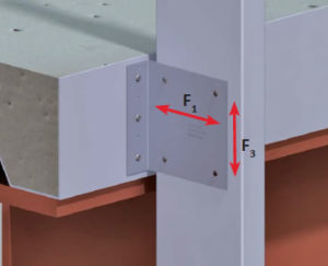
| Model No. | Stud Properties | F1 Allowable Loads (lbs) | F3 Allowable Loads (lbs) | ||||||
|---|---|---|---|---|---|---|---|---|---|
| Mils | Gauge | Fy (ksi) | 2 #10 Screws | 3 #10 Screws | 4 #10 Screws | 2 #10 Screws | 3 #10 Screws | 4 #10 Screws | |
| AC250 AC350 AC550 |
33EQS | 20 | 57 | 402 | 603 | 804 | 402 | 603 | 804 |
| 33 | 20 | 33 | 353 | 530 | 707 | 353 | 530 | 707 | |
| 43EQS | 18 | 57 | 635 | 952 | 1269 | 635 | 952 | 1269 | |
| 43 | 18 | 33 | 526 | 789 | 1052 | 526 | 789 | 1052 | |
| 54 | 16 | 50 | 1068 | 1602 | 1940 | 1068 | 1602 | 1940 | |
| 68 | 14 | 50 | 1510 | 1940 | 1940 | 1940 | 1940 | 1940 | |
| 97 | 12 | 50 | 1585 | 1940 | 1940 | 1940 | 1940 | 1940 | |
| 118 | 10 | 50 | 1585 | 1940 | 1940 | 1940 | 1940 | 1940 | |
| Maximum Allowable Clip Capacity | Max F1 = 1940 lbs | Max F3 = 1940 lbs | |||||||
| Model No. | Stud Properties | F1 Allowable Loads (lbs) | F3 Allowable Loads (lbs) | ||||||
|---|---|---|---|---|---|---|---|---|---|
| Mils | Gauge | Fy (ksi) | 4 #10 Screws | 6 #10 Screws | 8 #10 Screws | 4 #10 Screws | 6 #10 Screws | 8 #10 Screws | |
| AC750 | 33EQS | 20 | 57 | 804 | 1206 | 1608 | 804 | 1206 | 1608 |
| 33 | 20 | 33 | 707 | 1060 | 1414 | 707 | 1060 | 1414 | |
| 43EQS | 18 | 57 | 1269 | 1903 | 1940 | 1269 | 1903 | 1940 | |
| 43 | 18 | 33 | 1052 | 1578 | 1940 | 1052 | 1578 | 1940 | |
| 54 | 16 | 50 | 1940 | 1940 | 1940 | 1940 | 1940 | 1940 | |
| 68 | 14 | 50 | 1940 | 1940 | 1940 | 1940 | 1940 | 1940 | |
| 97 | 12 | 50 | 1940 | 1940 | 1940 | 1940 | 1940 | 1940 | |
| 118 | 10 | 50 | 1940 | 1940 | 1940 | 1940 | 1940 | 1940 | |
| Maximum Allowable Clip Capacity | Max F1 = 1940 lbs | Max F3 = 1940 lbs | |||||||
| Model No. | Stud Properties | F1 Allowable Loads (lbs) | F3 Allowable Loads (lbs) | ||||||
|---|---|---|---|---|---|---|---|---|---|
| Mils | Gauge | Fy (ksi) | 4 #10 Screws | 6 #10 Screws | 8 #10 Screws | 4 #10 Screws | 6 #10 Screws | 8 #10 Screws | |
| AC750 (with 2″ offset) |
33EQS | 20 | 57 | 804 | 1206 | 1608 | 804 | 1206 | 1550 |
| 33 | 20 | 33 | 707 | 1060 | 1414 | 707 | 1060 | 1414 | |
| 43EQS | 18 | 57 | 1269 | 1550 | 1550 | 1269 | 1550 | 1550 | |
| 43 | 18 | 33 | 1052 | 1550 | 1550 | 1052 | 1550 | 1550 | |
| 54 | 16 | 50 | 1550 | 1550 | 1550 | 1550 | 1550 | 1550 | |
| 68 | 14 | 50 | 1550 | 1550 | 1550 | 1550 | 1550 | 1550 | |
| 97 | 12 | 50 | 1550 | 1550 | 1550 | 1550 | 1550 | 1550 | |
| 118 | 10 | 50 | 1550 | 1550 | 1550 | 1550 | 1550 | 1550 | |
| Maximum Allowable Clip Capacity | Max F1 = 1550 lbs | Max F3 = 1550 lbs | |||||||
| Model No. | Stud Properties | F1 Allowable Loads (lbs) | F3 Allowable Loads (lbs) | ||||||
|---|---|---|---|---|---|---|---|---|---|
| Mils | Gauge | Fy (ksi) | 4 #10 Screws | 6 #10 Screws | 8 #10 Screws | 4 #10 Screws | 6 #10 Screws | 8 #10 Screws | |
| AC950 (with 2″ offset) |
33EQS | 20 | 57 | 804 | 1030 | 1030 | 804 | 1030 | 1030 |
| 33 | 20 | 33 | 707 | 1030 | 1030 | 707 | 1030 | 1030 | |
| 43EQS | 18 | 57 | 1030 | 1030 | 1030 | 1030 | 1030 | 1030 | |
| 43 | 18 | 33 | 1030 | 1030 | 1030 | 1030 | 1030 | 1030 | |
| 54 | 16 | 50 | 1030 | 1030 | 1030 | 1030 | 1030 | 1030 | |
| 68 | 14 | 50 | 1030 | 1030 | 1030 | 1030 | 1030 | 1030 | |
| 97 | 12 | 50 | 1030 | 1030 | 1030 | 1030 | 1030 | 1030 | |
| 118 | 10 | 50 | 1030 | 1030 | 1030 | 1030 | 1030 | 1030 | |
| Maximum Allowable Clip Capacity | Max F1 = 1030 lbs | Max F3 = 1030 lbs | |||||||
Screw shear values are based on the SSMA Screw Table with the following notes:
-
- The allowable loads are based on the steel properties of the members being connected, per NASPEC with AISI S100-07/S2-10 supplement.
- The nominal strength of the screw must be at least 3.75 times the allowable loads.
- Values include a 3.0 factor of safety.
- Penetration of screws through joined materials should not be less than 3 exposed threads. Screws should be installed and tightened in accordance with the screw manufacturer’s recommendations.
- Allowable loads indicated on the table(s) are for force in single direction only. If more than one force is applied to the connection, the designer shall provide the combined forces check as required by NASPEC with 2004 supplements.
- It is the responsibility of the designer to check the bending in the short leg of this clip.
- Details above indicate screw locations. Not all screw locations will have pre punched holes, refer to product drawing.
Quantity / Order Information
| Part No. | Width | Qty /Bucket |
Lbs /Bucket |
|---|---|---|---|
| AC250 | 2 ½” | 50 | 23 |
| AC350 | 3 ½” | 50 | 29 |
| AC550 | 5 ½” | 50 | 41 |
| AC750 | 7 ½” | 50 | 52 |
| AC950 | 9 ½” | 35 | 45 |
Note: Additional lengths available upon request.