
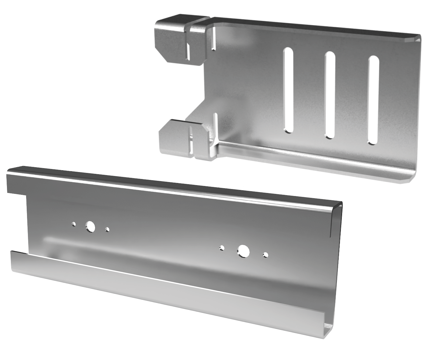
The DRC drift rail clip is a two piece system consisting of a DR drift rail that is mounted to the building structure. The inserted clip DRC allows vertical deflection and lateral drift of the building structure. This system allows for the clips to be rotated into place at any point along the rail. The DR drift rail and the DRC drift rail clip are formed using 97mil (12GA) galvanized steel.
Features & Benefits
- No pre-determined clip layout required with the use of the DR drift rail
- Ease of installation with the DR pre-punched anchor holes:
- Single 0.438” and two 0.188” holes spaced at 6” o.c.
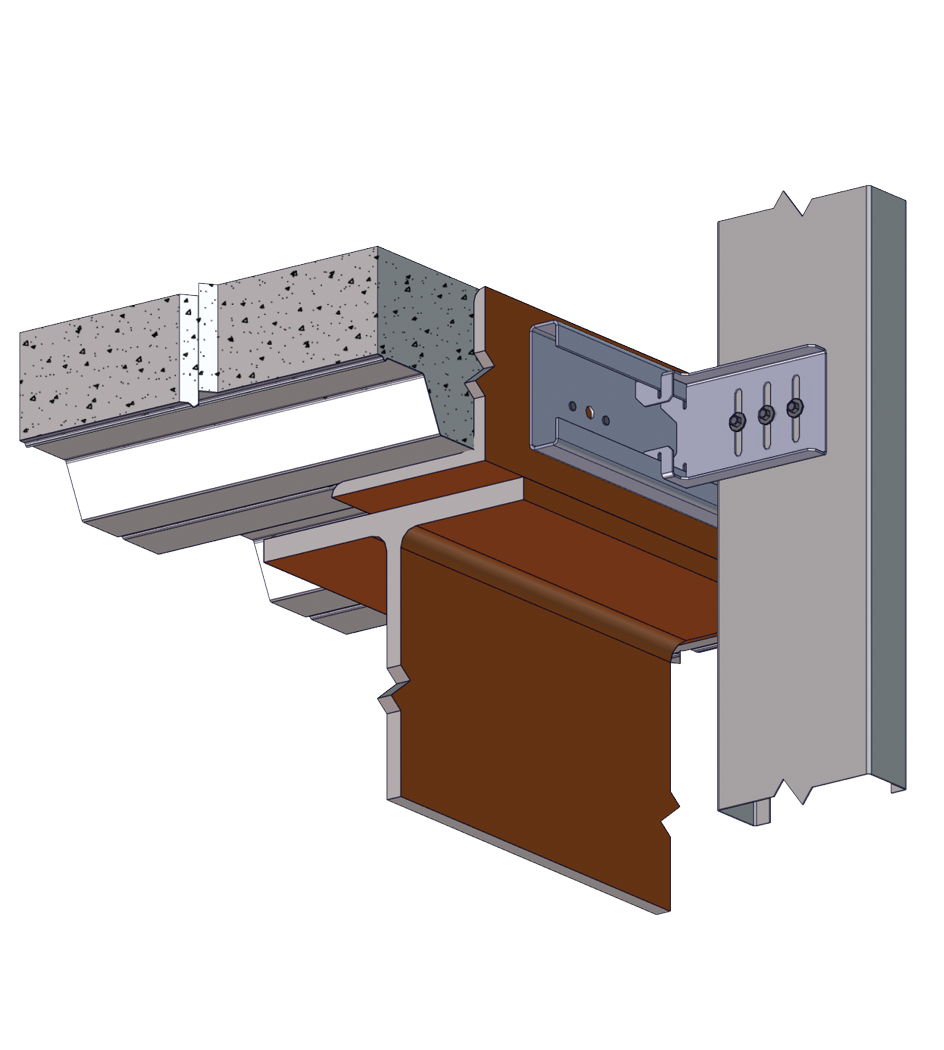
- Transfers horizontal load into structure, while allowing for horizontal structural movement
- DR flanges are pre-punched with weep holes at 6” o.c.
DR & DRC Submittal Download
Material Composition
- Mill certified steel
- ASTM A653/A653M
- Clip
– 97 mil material thickness
– 57 ksi yield strength
– 65 ksi tensile strength
– G90 galvanized coating - Rail
– 97 mil material thickness
– 57 ksi yield strength
– 65 ksi tensile strength
– G90 galvanized coating - #14 Shouldered screw
– ASTM C1513
– C1022 case hardened steel
– Zinc plated coating
– 1000 hours salt spray life
– Exceeds standard screw life by over 10X
Allowable Loads
| Part No. | Allowable Loads (lbs) F1/F2 Direction (See Illustration) | ||||
|---|---|---|---|---|---|
| Stud Properties | 2 #14 Screws | ||||
| Thickness (mil) | Gauge | Fy (ksi) | F1 (lbs) | F2 (lbs) | |
| DRC 350 |
33EQS | 20 | 57 | 485 | 510 |
| 33 | 20 | 33 | 485 | 510 | |
| 43EQS | 18 | 57 | 502 | 621 | |
| 43 | 18 | 33 | 502 | 621 | |
| 54 | 16 | 50 | 502 | 935 | |
| 68 | 14 | 50 | 502 | 1054 | |
| 97 | 12 | 50 | 502 | 1054 | |
| 118 | 10 | 50 | 502 | 1054 | |
| Part No. | Allowable Loads (lbs) F1/F2 Direction (See Illustration) | ||||||
|---|---|---|---|---|---|---|---|
| Stud Properties | 2 #14 Screws | 3 #14 Screws | |||||
| Thickness (mil) | Gauge | Fy (ksi) | F1 (lbs) | F2 (lbs) | F1 (lbs) | F2 (lbs) | |
| DRC 550 750 950 |
33EQS | 20 | 57 | 485 | 510 | 588 | 784 |
| 33 | 20 | 33 | 485 | 510 | 588 | 784 | |
| 43EQS | 18 | 57 | 502 | 621 | 588 | 1006 | |
| 43 | 18 | 33 | 502 | 621 | 588 | 1006 | |
| 54 | 16 | 50 | 502 | 935 | 588 | 1353 | |
| 68 | 14 | 50 | 502 | 1054 | 588 | 1353 | |
| 97 | 12 | 50 | 502 | 1054 | 588 | 1353 | |
| 118 | 10 | 50 | 502 | 1054 | 588 | 1353 | |
Table Notes
- Allowable loads are minimum of ASD allowable loads from testing and 1/8″ relative deflection service limit.
- Allowable loads are for connection of Drift Rail Clip (DRC) to stud only.
- Allowable loads have not been increased for wind, seismic activity, or other factors.
- Allowable loads indicated on the table(s) are for force in single direction only. The designer shall use the combined forces check as required by AISI S100 if more than one force is applied to the connection.
- Attachment and Anchorage of the Drift Rail (DR) to structure is to be designed by others.
Quantity / Order Information
| Part No. | Width |
|---|---|
| DRC350 | 3 ½” |
| DRC550 | 5 ½” |
| DRC750 | 7 ½” |
| DRC950 | 9 ½” |
All DRC clips include shouldered screws. Additional lengths available upon request.